Elements of Drilled Construction
I started my training in drilled construction when I worked with Don Morin and his Hughes “digger” in Seattle, Washington, in 1960. The project was a soldier pile shoring wall with the piles set in holes pre-drilled with the “digger.”
The Hughes “digger” is the workhorse of foundation drilling. A large truck pulls a tower and a hydraulic power plant behind the operator’s cab. When traveling, the tower is laid down over the truck cab. The tower is raised to vertical when preparing to drill. Inside the tower is a Kelly bar attached to an auger. The whole apparatus sits on a turning table behind the cab. The table permits the tower to swing through an arc from the back of the truck to the side of the truck. This helps with quick setup over a proposed hole. Drilling proceeds by turning and pushing down with the auger on the Kelly bar. The auger is lifted and spun to discharge the soil cuttings. This procedure is repeated until the intended depth is achieved.
Don Morin created the Association of Drilling Contractors in 1974. Paul assisted Don in this effort and served as the technical resource for ADSC for many years.
The Hughes “digger” is designed to make holes up to about 20 feet deep and up to 30 inches in diameter. Apparatus and larger models are available if needed. We have experience with shafts up to 100 feet deep and 10 feet in diameter.
Once the shaft is drilled, a rebar cage as specified by the structural engineer is lowered vertically into the shaft, and the shaft is filled with concrete. The complete installation is a reinforced concrete column in the ground.
The soil mechanics of drilled shafts comes in two varieties: end bearing and friction. Test borings will reveal the types of soil to be encountered, and laboratory soil tests will reveal the soil cohesion or friction angle.
For shafts bearing on clay, the bearing capacity is found by applying Meyerhof’s equation 9C PSF.
For frictional soils, the standard Terzaghi method for bearing capacity can be used.
Another variable of consideration is the depth of the groundwater table. If groundwater is higher than the planned shaft depth, a steel casing may be used to keep the hole open.
If a casing is used, a hole is first drilled to start the casing. Drilling then proceeds, and the casing sinks or is tapped in to follow the auger. As concrete is placed, the casing is withdrawn by cable tension.
Drilled shafts taken bearing on rock can be a special case. Often, the rock is as hard as concrete or more so. In that case, the shaft can stop directly bearing on the rock. For softer rock formation, laboratory tests are recommended.
Bridges are commonly supported on columns that are placed across the river or span of the sea. Shafts are quite suitable for support of these columns and often can just be a vertical extension of the shaft. Paul was the engineer for DMB Contractors for ten years from about 1961 to 1970. During this time, Paul designed and DMB installed numerous soldier pile excavation supports.
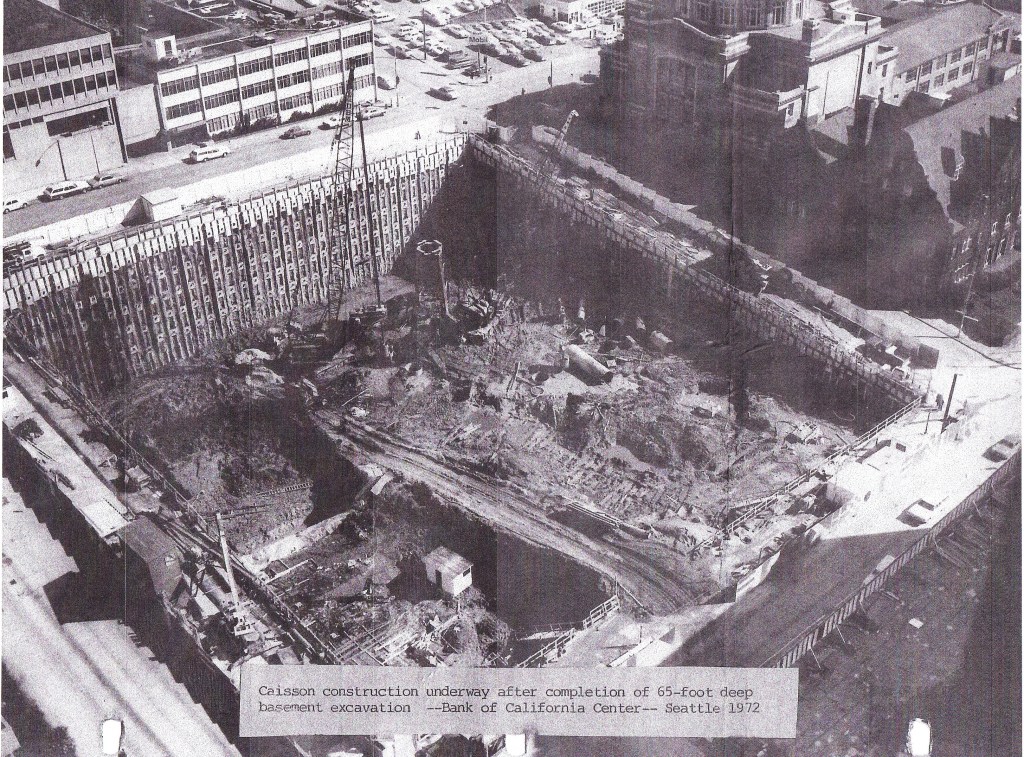
Drilled shafts for shoring are specified with a shaft diameter to accommodate a steel wide flange beam set in vertical holes. Our work with DMB involved work in 30 states and included the 65-foot deep excavation encompassing a city block in Seattle, Washington.
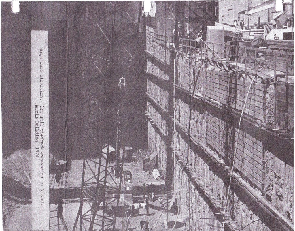
For five years, we operated an engineering practice in Atlanta, Georgia. Much of our work was generated by the construction of the MARTA rail system but also included buildings and highway bridges. One of our notable projects was excavation support for the 50-foot deep Harris Building basement. This work involved one of our most challenging installations: underpinning a nine-story brick wall on the very edge of the pit. DMB did this by drilling an angled shaft with the top beside the brick building footing and the bottom vertically under the footing. A beam was then inserted and blocked under the footing. The setup was carefully monitored on a daily basis to note any potential damage. There was none.
Elements of Soil Structure Interaction
One of the fundamental laws of physics goes like this: for every action, there is an equal and opposite reaction. This applies to soil just as it does to concrete and steel. The footing pad pushes down on the soil, which responds by compressing according to its geotechnical characteristics. The steel beam bends or the concrete cracks when the applied load (action) exceeds the carrying capacity of the material (reaction).
Soil friction interaction can be used to reduce the amount of material and effort that is required in a given situation. The key factor involves the geotechnical characteristics of the soil.
Now, soil is the most variable and changeable of construction materials. Steel tension is known within pounds for a particular composition. Compressive strength of concrete is routinely tested on the job site. Soil is another matter.
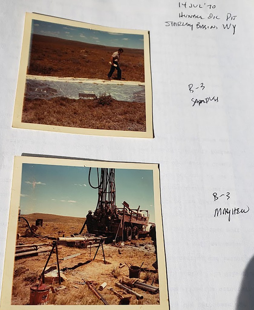
Terzaghi and a handful of early researchers laid the groundwork for those of us who practice. The use of the two-inch split spoon sampler to obtain SPT and very disturbed samples for lab tests comes from these early pioneers. Modern design pushes us into dealing with higher boards and more sensitive structures. This is where soil structure interaction comes into play. The split spoon sampler is out. Tests on disturbed soil samples are no longer adequate to the case.
Engineers have studied the means of obtaining undisturbed soil samples for decades. Wildly unusual methods have included freezing the ground before carving out a sample to extracting a block of soil and then trimming it down to test size—typically 2.5 in diameter by 6 inches long. These methods have seldom been used outside of university research. The truth is that obtaining undisturbed soil samples is seldom achieved.
There are two cases where there have been suitable results: first, with very soft clay, and second, with stiff clay to soft rock deposits. With soft clay, the Norwegians have developed a method using thin tubes pushed into the soil. Even then, the soils engineer is confronted with a delicate material that is not easy to test. Samples of stiff clay or hard rock are much easier to obtain using the Pitcher Sampler. A brief description of this device follows this monograph.
What the geoengineer is after in preparation for soil structure interaction is cohesive friction angle and modulus. The vehicle to apply the soil parameters is Fine Element Method (FEM). Professor Clough formerly of Stanford University developed the guiding method, and we have used it successfully on major projects.